
Abhisek (hakarabhi@gmail.com)
My dear friend late Amir Shrestha
|
Nurse Calling System Abhisek (hakarabhi@gmail.com) My dear friend late Amir Shrestha |
|
Table of Contents
Introduction
Detailed Design
Task Distribution
Hardware Design
Software Design
Results
Struggle
Conclusion
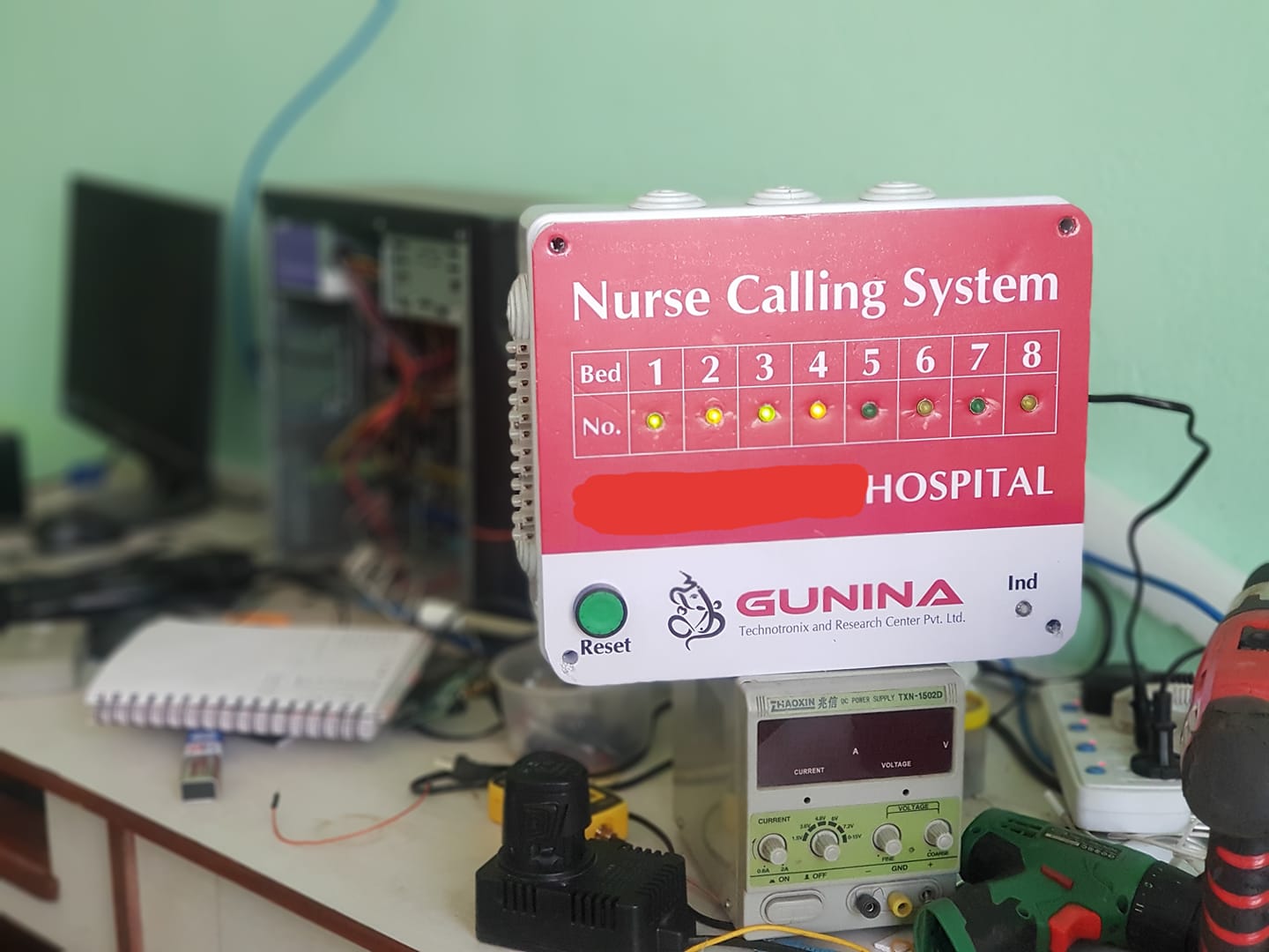
Project-"Nurse Calling System" allows communication between a healthcare provider and the people they serve, allowing healthcare providers to serve their patients more attentively and efficiently. This project is a team effort to build nurse calling unit for hospitals, old-age homes, care centers, etc that is cost efficient, scalable and reliable. The project is inspired by individual experience of a team member while taking care of his grandmother at hospital. The requirement to reach nurse's ward to call her during difficult and emergency situations leaving the patient on her own and the delay in service due to this process motivated the team to develop the project. Hospitals and care centers when asked about implementing Nurse Call Systems, argued they can't afford sophisticated ones, if they bought one, there would be no maintenance service from the brands available in the market. Also market available nurse call systems were not customizable according to their wards and rooms, instead the wards must be arranged according the nurse call systems, also scalability with a bought product was not available. These factors pushed the team to build a Nurse Calling System that is relaible, scalable and affordable. Also, the maintenance service now is just a door away.
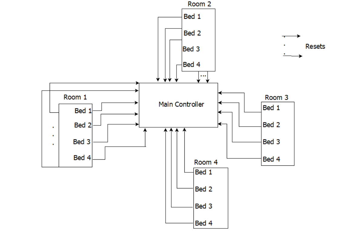
Nurse Calling System was actually first implemented by Florence Nightingale in the 1850s. That involved placing hand bells at bedsides so patients could ring the bell for assistance and nurses at nurse station could reach them to serve. We modeled our system in similar fashion. Our system included a master station at nurse's ward and multiple client units at patients' rooms. Each client unit is linked to the master unit via wire or wireless depending on the requirement. Every client unit included individual pushbuttons for each bed. Patient could push the button to call the nurse. Individual beds in room had respective pushbuttons to call the nurse. The pushbuttons were hardwired to the client unit in each room. If a ward/room had less beds, a single client could serve multiple such rooms.
There was also another reset button in individual patient's bed which the nurse could push only after the pateint is served. This made nurses more accountable and boosted patient and employee satisfaction and morale.
The master unit at the nurse's ward included bulbs for each beds so nurse could identify each room and bed easily. Also, the master unit included an alarm unit to notify an emergency situation. The emergency mode is trigerred when the patient pushes the pushbutton three or more times. When the pushbutton is pushed three or more times, the bulb linked with that individual bed blinked with 50% duty cycle. Also the alarm would blow. This notified the situation is an emergency and the nurses could rush to the respective room and bed.
| Task | Amir | Abhisek | |
| Board Planning & Sketching | 30% | 70% | |
| PCB Designing | 20% | 80% | |
| PCB Printing | 60% | 40% | |
| Circuit Designing | 0% | 100% | |
| Voltage Regulation | 0% | 100% | |
| Switching Algorithm | 25% | 75% | |
| Microcontroller Programming | 20% | 80% | |
| Wiring | 60% | 40% | |
| Drilling | 70% | 30% | |
| Commercial Planning | 30% | 70% | |
| Field Visit | 50% | 50% | |
| Fun Making | 100% | 0% |
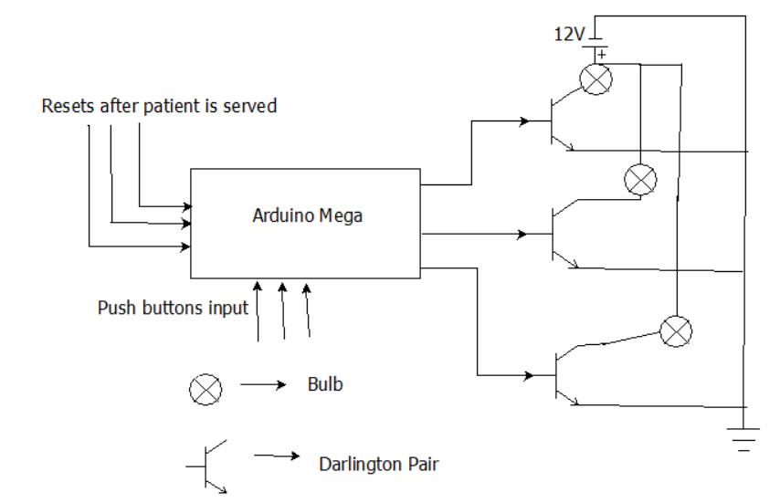
The project started with designing a control board that is capable of switching the bulbs very fast and is fast in communication between client units and master unit. To make the system more reliable and fast we first opted a wired connection between client units and master unit. Ethernet wires were used for communication between them. The master control board implemented a central microcontroller, switching units and output units (display units). The switching unit included transistors as a darlington pair to switch high current drawing bulbs rapidly. The microcontroller when trigerred by pushbuttons from client units sends a high control signal to the 2N5686 NPN used darlington pair which drives the power bulbs. NPN transistors as darlington pair were used instead of mechanical relays because these semiconductor devices are faster. A darlington pair was used instead of a single transistor because of its high current gain such that it drives a high current drawing load wih significantly low control signal compared to a single NPN transistor.
Darlington Pair
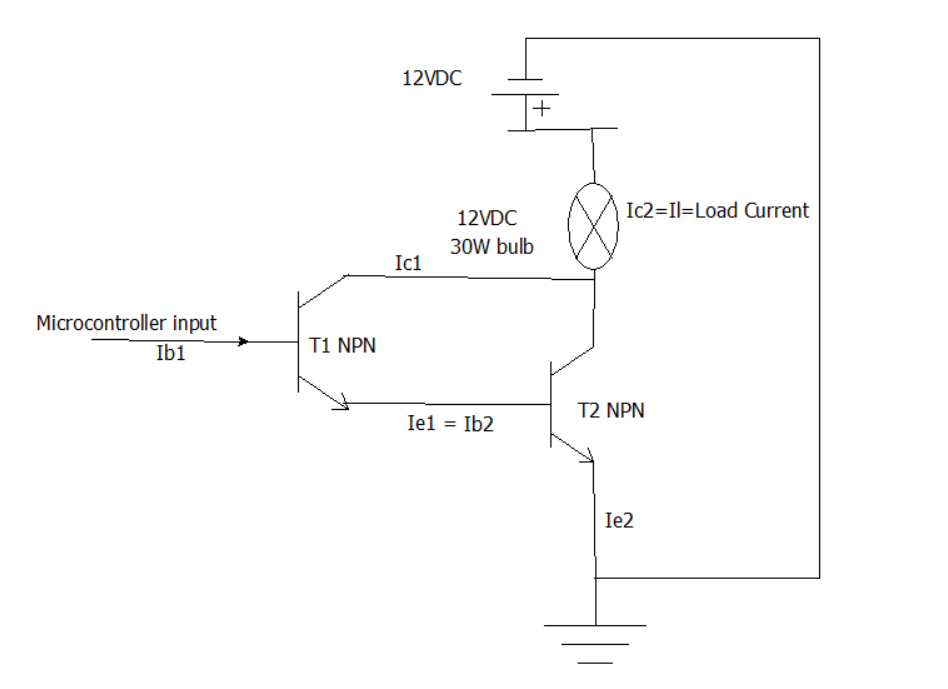
Darlington pair can simply be visualized as a single NPN transistor. It is formed by connecting the emitter terminal of one NPN transistor to the base of another NPN transistor and the collectors of both transistors are tied together. So the overall circuit seems to have one common collector, one base and a single emitter. There is a different level of complexity in reality but visualizing the circuit this way helps to understand it better.
Darlington pair compared to single NPN transistor drive significantly high power loads with low control signal such that microcontroller's output can drive the load. For a single NPN transistor, as we have in our case 30W bulbs as load in collector terminal of transistor, for 12VDC input, Ic = Load Current = (30/12)= 2.5A. For a current gain of transistor (β) = 100, the base current required to saturate the transistor and operate it in closed switch mode is Ib=(Ic/β)=(2.5/100)= 25mA which is about maximum current for a digital pin of a 5V microcontroller. Therefore a microcontroller might not be able to switch On the transistor.
Making two 2N5686 NPN transistors as darlington pair solved the issue. For two NPN transistors when used as darlington pair, from the figure above, we see the base current for transistor T1 = Ib1, the collector current for transistor T1 = Ic1, and Ic1 = β1Ib1, the load current Il = Ic2. The emitter current for transistor T2 is Ie2, the emitter current for transistor T1 = Ie1 = transistor T2 base current = Ib2. It is clear for transistor T2; Ic2 = β2Ib2. The total collector current Ic = Ic1 + Ic2 = β1Ib1 + β2Ib2 = β1Ib1 + β2Ie1 = β1Ib1 + β2(1+β1)Ib1 = (β1+β2+β1β2)Ib1, so Ic/Ib1 = (β1+β2+β1β2); β1β2 > (β1+β2) so Ic/Ib1 = β1β2; if β1 = 100, β2 = 100; Ib1 required from microcontroller in this case becomes Ib1 = (Ic/β1β2) = (2.5/10000) = 0.25mA which is easily provided by the microcontroller. Thus, a choice of darlington pair was made.
Hardware Design + Microcontroller
Microcontroller programming made the logic execution very flexible. A single master unit with a single microcontroller was established at nurse's ward. And client units were the pushbuttons at the patients room which were hard wired to master unit. Master unit included light bulbs and alarm unit. However when wireless communication was adopted between push buttons and central master unit, two arduinos were used as microcontrollers in the system as master unit and client units. Arduino Mega was implemeneted as master unit and Arduino Uno was implemented as client unit. If required multiple client units were used. These client units communicated to master unit via UDP protocol. Client units were connected to router, and master unit was also connected to router via ethernet cable. Thus assigning IP addresses to he clients and master units made communication between these units possible in the LAN network.
PCB Design
PCB design was done in a free open source platform KiCad.
Voltage Regulation
We stepped down 220VAC to 12VDC using a 220-12, 5A transformer and full bridge high power diode rectifier circuit. The 12VDC was able to drive the control board and the bulbs. However, push buttons needed 5V(ground can also be used), microcontroller if Arduino UNO is used required 5V if possible, 12V for it is its upper limit. So well regulated supply was needed. 7805 ICs with 7809 ICs and couple of capacitors and resistors did the job to regulate supply to almost every unit in the board. Arduino Mega operated in 9v.
We implemented a simple switching algorithm in software. The algorith wa simple when wired communication channel was used. Whenver the pushbutton was pushed, the bulb should glow and when the nurse provides service, she could reset the bulb to OFF using other push button. If pushbuttons were pushed three or more time in a single go, the emergency mode is trigerred that is the microcontroller sends control signal of 50% duty cycle. The bulb would blink in this mode. Nurse could rush into the parient's room, serve him/her and then reset the emergency mode. The buzzer would also blow in emergency mode. If wireless communication channel is adopted, then few more codes must be added to operate ethernet shields with arduino and communicate using them.
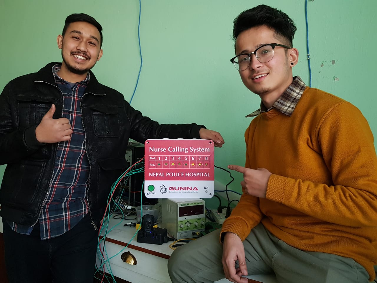
Our project was successfully completed, it was installed at Nepal Police Hospital. There was several problems were hard wiring the push buttons to the master unit because of asthetic values of hospital. That was solved in some floors using wireless mode of communication and in other floors using duct to hide the wires.
The technical struggle again was beautiful. But working as a fresher to get your products installed was challenging. Convincing the AIG of police hospital was not easy. The darlingtons were not so darling but were later made to work out. A fresher's commercial life was tough but the learning curve was massive. That's life.
The system design can be made much compact and aesthetically convincing. We lacked that aspect. The system can include other features to it too but that would complicate the simplicit of our system. Maybe we can work that out in near future.