Abhisek Adhikari(hakarabhi@gmail.com)
My dear friend late Amir Shrestha
Diwakar Dhungana

|
Project- Load Switching & Sharing Abhisek Adhikari(hakarabhi@gmail.com) My dear friend late Amir Shrestha Diwakar Dhungana |
|
Table of Contents
Introduction
Detailed Design
Task Distribution
Hardware Design
Software Design
Results
Field Deploy
Struggle
Conclusion
Project-"Load Switching and Sharing" is a process of technical tuning of our first year project- Water Level Indicator and Controller and final year project- Power Supply Management and Load Profile Monitoring. It is a combined effort of the team to design, develop and realize control board that switches loads and displays their status including their health. Our project is inspired by the water situation in residential areas of Kathmandu. The Nepalese Government Central Bureau of Statistics has provided the data that daily demand of water in Kathmandu is 360 million litres(as of 2017), but the supply is less than half and water wastage via leakages, overflow and spillage adds up to 35% of that being supplied. Water management is a must in Kathmandu where supply is already less. Our project- "Load Switching and Sharing" fits perfectly in water management scenario where loads as pumps can be switched on and off both automatically and manually as and when needed with digital displays constantly giving an idea about the levels of water, health of overall system, alarm warnings, etc. This project in a larger picture helps reduce water inequity in Kathmandu.
For our first year engineering project we developed a similar but hardware only version of load switching circuit. The hardware only design worked on transistor logic and unfortunately was erratic and also vulnerable to changes in volatge levels. It required protection units, regulated supply units and adapting the hardware design according to the number and type of loads demanded separate board design everytime. This microcontroller based load switching and sharing unit is software + hardware implementation that is well immune to voltage instability and more importantly very flexible to changes in number and type of loads. To design the control board, we first sketched each units: sensor units, supply unit, logic unit and relay unit and accommodated them with a goal to achieve smaller form factor. The circuit was designed in KiCad,a free and open source platform. The microcontroller was selected as per the project's duty, however most of the time Arduino Mega-2560 did fine. The sensor unit employed float sensors to provide status of water levels and Ethernet Cables were communication channel between sensors and control board. Ethernet cables have minimal voltage drop over the length of cables and worked perfectly for the project. To control the loads, algorithms were developed acording to the type of operation, number and variety of loads. The microcontrollers were programmed accrodingly. The switching unit includes BC547 NPN transistors, 5V relays, 12V relays via which loads were switched/shared.
We started the project hiring a fund provider, Guinina Technotronix helped us with initial funding for 20 products, with 10% share on profit in each product.
| Task | Diwakar | Amir | Abhisek | 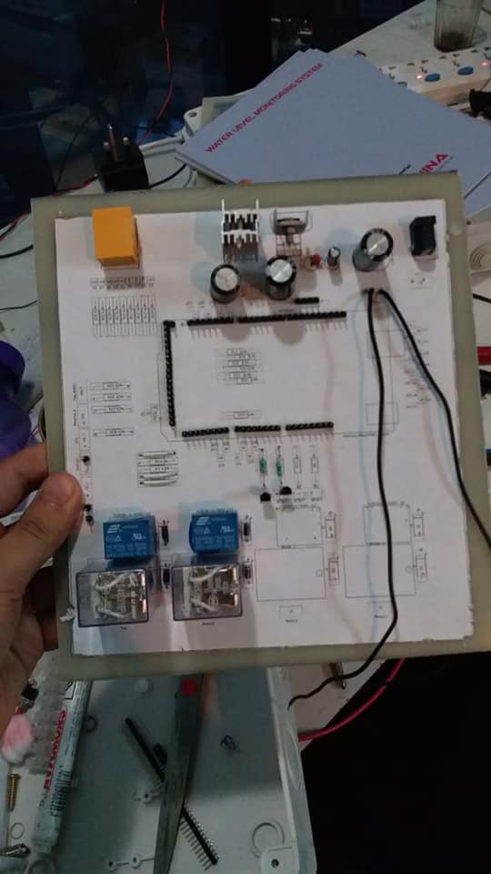 |
| Board Planning & Sketching | 60% | 0% | 40% | |
| PCB Designing | 60% | 0% | 40% | |
| PCB Printing | 60% | 10% | 30% | |
| Circuit Designing | 40% | 0% | 60% | |
| Voltage Regulation | 50% | 0% | 50% | |
| Switching Algorithm | 25% | 0% | 75% | |
| Microcontroller Programming | 20% | 0% | 80% | |
| Wiring | 30% | 60% | 10% | |
| Drilling | 40% | 40% | 20% | |
| Commercial Planning | 40% | 20% | 40% | |
| Field Visit | 30% | 30% | 40% | |
| Fun Making | 5% | 90% | 5% |
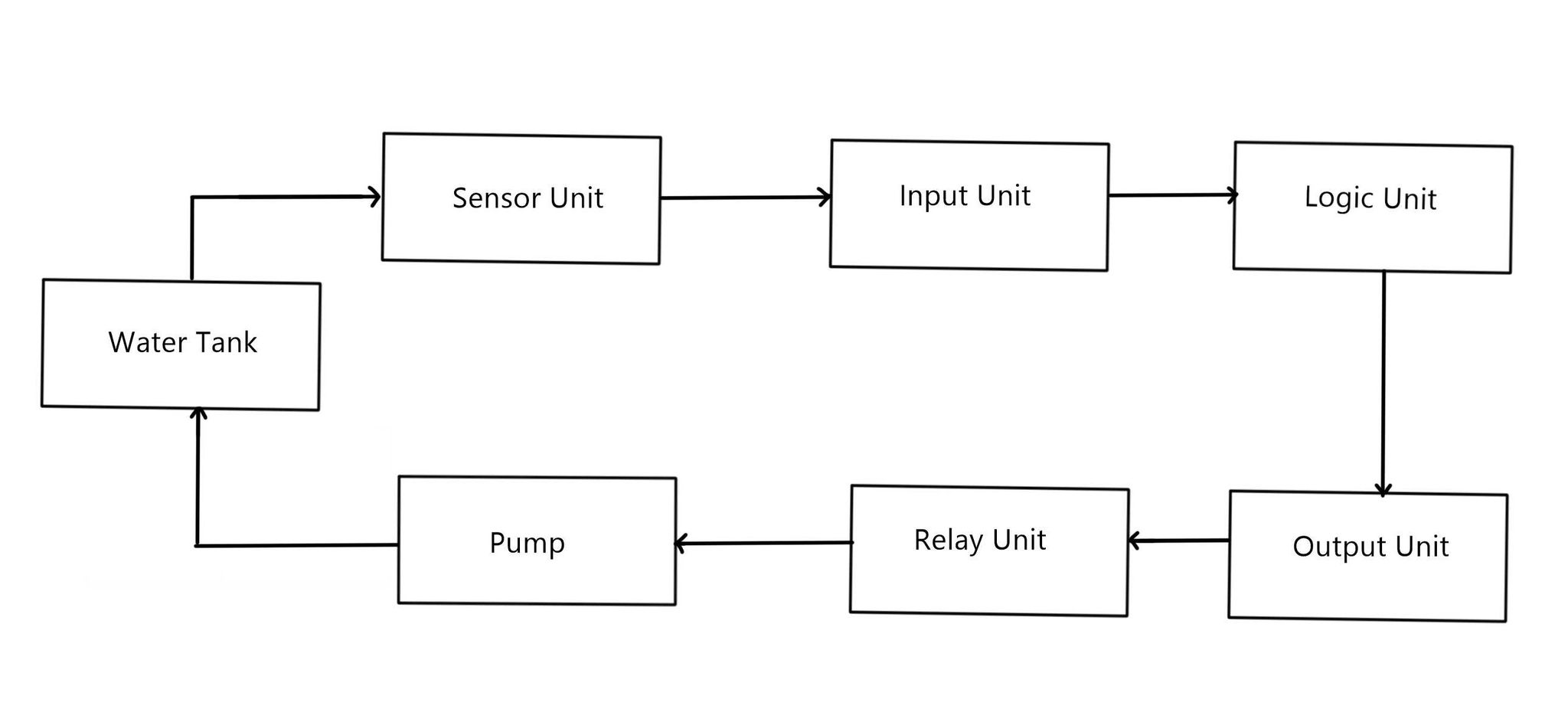
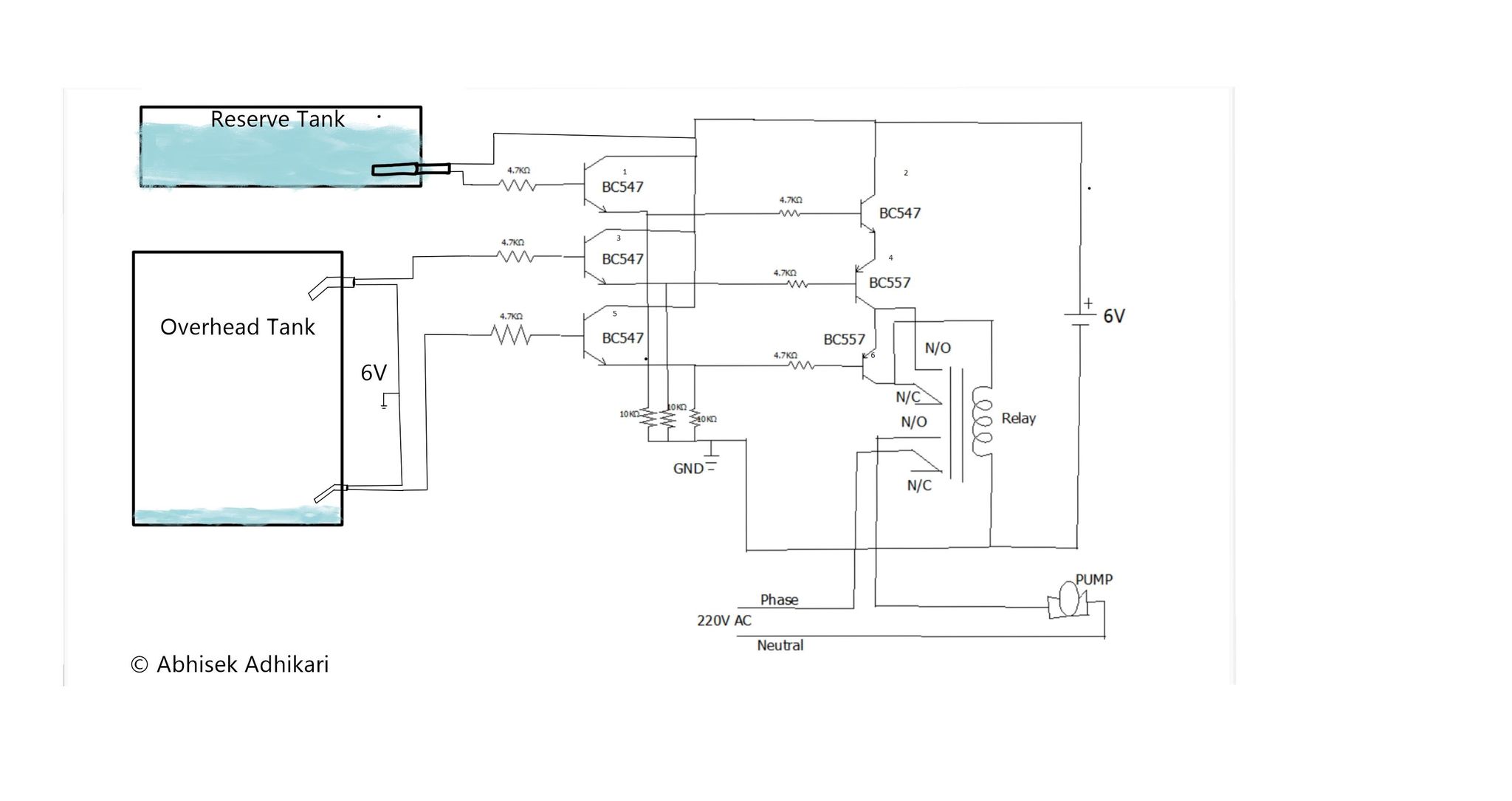
In the overhead tank, we used two sensors, high level sensor to indicate upper level of water in the tank, low level sensor to indicate lower water level in the tank. Two transistors; one NPN and other PNP were used for both high and low level sensors.
From the figure below, we can see how the logic we wanted in our system is derived. Once the reserve tank’s sensor detects enough water level, it feeds the biasing voltage to the BC547 (1). The 4.7KΩ resistor limits the current to required biasing current enough to operate the transistor(1) in saturation mode. Once this transistor(1) operates in saturation mode, collector and emitter are short circuited. Thus, 6V from collector of transistor(1) switches to its emitter which is then fed to BC547(2) via 4.7KΩ resistor. This injects enough biasing current to operate transistor(2) in saturation mode. Then the collector and emitter of transistor(2) are short circuited. 6V from collector of transistor(2) reaches to its emitter which is fed to emitter of transistor BC557(4). However this 6V from BC557(4) emitter is not yet switched to its collector. Now, lets observe the overhead tank, in the overhead tank, if the tank is full i.e, if the upper sensor level is met by water level then the 6V from sensors is fed to the BC547(3), which injects biasing current to the transistor(3) and the collector and emitter of transistor(3) is short circuited. Thus 6V from collector of transistor(3) reaches to emitter which is fed to the base of transistor (4) BC557. Since BC557 is PNP transistor, due to 6V at its base terminal and 6V which initially arrived at its emitter terminal via reserve tank’s transistors, it won’t switch ON. BC557 being a PNP transistor, only switches ON when there is ground at its base terminal. So, when the water level in overhead tank falls below upper sensor level, the upper level sensor now does not feed 6V to BC547(3). This leads BC547(3) to switch off, it now operates in cut off region. Thus ground which is already connected to emitter of BC547(3) via 10KΩ resistor is now fed to base terminal of BC557(4). Ground at base terminal of BC557(4) and 6V at its emitter causes it to inject enough biasing current from emitter to its base, now BC557(4) operates in saturation mode and is switched ON. Its emitter and collector are short circuited, 6V from its emitter reaches to its collector. And then 6V reaches to emitter of BC557(6) as its emitter is physically tied to collector of BC557(4). However this 6V from emitter of BC557(6)does not reach its collector and to the relay. To achieve this, the water level in the tank must fall below lower sensor level. Once the water in the tank falls below lower sensor level, BC547(5) is switched off, ground tied to its emitter via 10KΩ resistor is fed to BC557(6). BC557(6) being a PNP transistor, has ground at its base and 6V at its emitter terminal so it injects biasing current from emitter to its base and operates in saturation mode. It is switched ON. Thus 6V from BC557(6)’s emitter reaches to its collector and then to the coil of relay as shown in the figure below. 6V and ground is between relays coil, the relay’s Common point switches from Normally Cosed (N/C) to Normally Open (N/O). The 6V relay has a pair of "Common N/C N/O" arrangements. In the upper Common N/C N/O arrangement, as we see in figure below, the N/O terminal already has 6V from BC557(4)’s collector terminal and its common terminal is connected to relay’s coil. This arrangement is done to latch the relay even if water reaches the lower sensor level and keep the pump turned ON until water reaches upper sensor level. So, once the relay turns ON,the 220VAC from lower common terminal of relay connects to lower N/O terminal of relay and 220VAC is fed to the pump and pump turns ON and fills the overhead tank. First the water level reaches the lower sensor level, this causes lower sensor level to feed 6V to base terminal of BC547(5). BC547(5) now operates as closed switch, it feeds 6V from collector to its emitter which reaches to base terminal of BC557(6). 6V at base terminal of BC557(6) causes it to operate in cut off mode. So 6V is no longer available at its collector terminal and relay’s coil does not get its 6V from there. But pump needs to remain ON until water reaches upper sensor level. So the previously discussed latching of relay is done. As we see in figure, once the relay was switched ON, its common and N/O were connected, the upper N/O is physically connected to collector of BC557(4) which still has 6V. This 6V is fed to relay’s coil via N/O to Common terminal to relay’s coil as seen in figure. Thus, even if water level goes above lower sensor level, pump does not turn off. Now pump gradually fills the overhead tank, and as upper sensor level is reached, 6V from sensor is fed to base of BC547(3) and it injects biasing current enough to operate BC547(3) in saturation mode. 6V from its collector reaches its emitter and this 6V from its emitter reaches to base of BC557(4) which causes BC557(4) to switch off. Now its collector and emitter are opened so 6V is not reaching its collector and upper N/O terminal of relay has no 6V which leads 0V at relay’s coil. This turns off the relay, common terminals of relay are now connected to N/C terminals and pump no longer gets its 220VAC. The pump is turned off and water is not fed to overhead tank and prevents the overflow. This way we got our logic implemented in the system.
The sensor wires connecting sensors and transistors are ethernet cables. The logic worked perfectly, however if any changes in logic was needed, a separate circuit set up was required. This made the job repititve. Also the circuit needed good preotection against minor voltage flucatuations too. It added extra burden and required great delicacy in designing the control board.
Hardware Design + Microcontroller
The microcontroller programming made the logic implementation very flexible, it is also self immune to voltage fluctuations. However, it increased the cost but flexibilty was a good bargain. The microcontroller programming replaces the transistor logic. Arduino Uno, Mega-2560 were chosen accroding to complexity and burden of project. Raspberry pi could also be used if larger projects required fast wireless networking among control boards. Every options were made available in control board design.
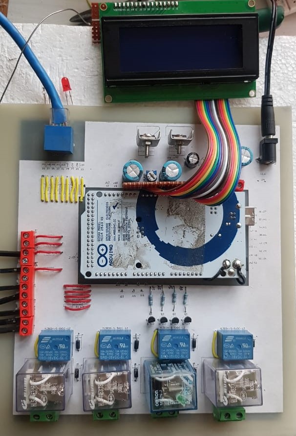
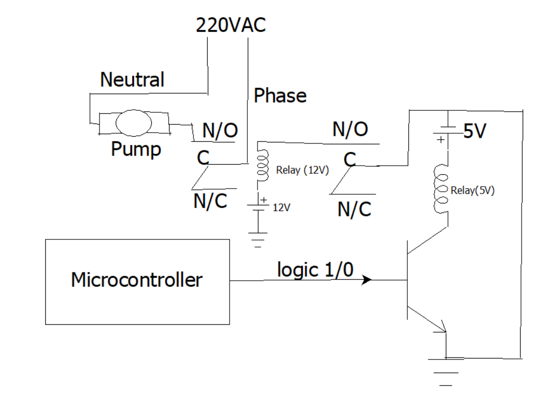
Microcontroller took the center of board. It fed logic to a BC547 NPN transistor. BC547 switched ground from its emitter to 5V relay connected in collector. 5V relay went from Common-N/C connection to Common-N/O connection which transferred ground to the coil of 12V relay via its N/O connection. 12V relay then switched AC loads.
It is critical that all the circuit components; microcontroller, transistors, relays, lcd display unit have common ground. Else unimaginative things happen. In the circuit 12V has its ground common to 5V supply, it is just messy to show it there. Sorry! A flyback diode is essential for inductive loads like relay. We forgot to show it in the circuit. Also, NPN transistors in common emitter configuration must have load at collectors. If emitter has load connected to it then only 5V from microcontroller might be unable to drive the loads like relay.
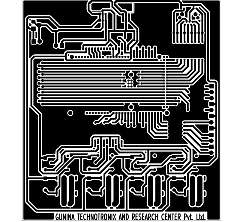
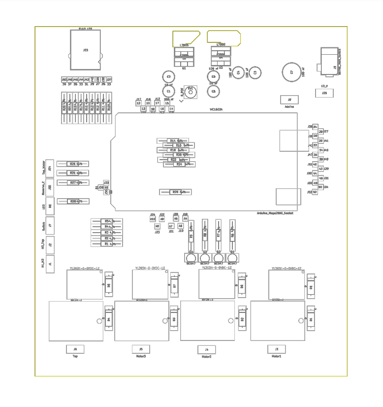
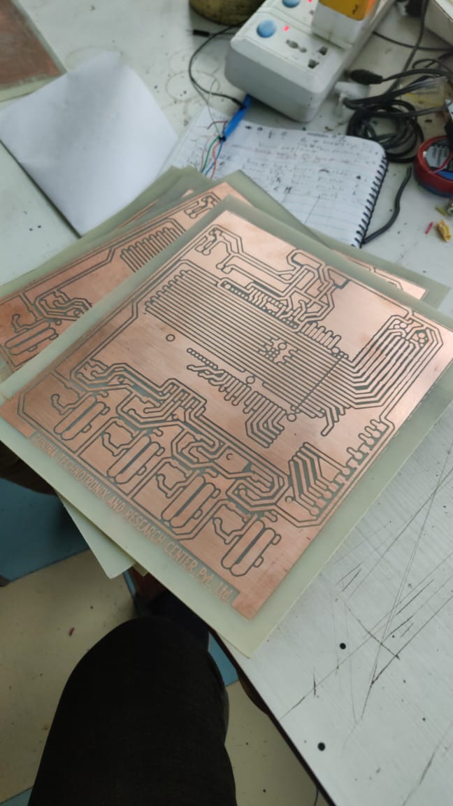
PCB Design
PCB design was done in a free open source platform KiCad, however printing the PCB in custom made lab was a tough task to do. After the printing, drilling the PCBs to fix the circuit components was not easy. We cleaned an old drilling machine with Kerosene, cut some tyre tubes to make the belt of the drilling machine. And finally we were good to go.
Voltage Regulation
We stepped down 220VAC to 12VDC using a transformer and full bridge diode rectifier circuit. The 12VDC was able to drive the control board. However, sensors needed 5V(ground can also be used), the 5V relay required 5V, the LCD unit was sensitive to voltage fluctuations and required stable 5V, microcontroller if Arduino UNO is used required 5V if possible, 12V for it is its upper limit. So well regulated supply was needed. 7805 ICs with 7809 ICs and couple of capacitors and resistors did the job to regulate supply to almost every unit in the board. Arduino Mega operated in 9v.
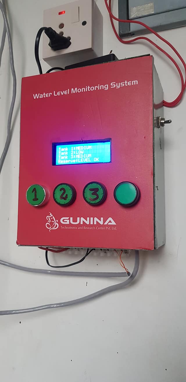
We implemented a simple switching algorithm in software. It also included display codes to give user an idea about status of the environment and loads here, level of water and status of pump. The algorithm was three state finite state machine, where the first state was when water in tank is full so both the float sensors are providing ground to the control board. The system would enter the second state when water level falls and the upper float sensor now does not provide ground to the control board. Still the pump is in OFF state. Only the display unit shows different level of water in the tank. The system reaches third state when water level falls below the lower float sensor. This state switches the pump ON and it is turned OFF only when water pushes both float sensors. Also we had toggle mode between manual and automatic modes so user can intervene as and when required.
Our project was technically successful. We used the control boards to switch a range of loads implementing different sensors. Few examples include: pumps, conveyer belt motors, stage lights,and more. Our control board was adaptable to different sensor units and different loads. But we had several challenges while designing. Printing a good PCB was not that easy. Also we had several problems when communicating channel were normal wires between sensors and control board. We later used Ethernet Cables. Drilling a PCB was not that easy too, we could not afford a brand new drilling machine. We refurbished an old one. Also transistors and LCDs were tricky thing to work on. But eventually we grasped them all.
Still much can be done and integrated to the control board. Form factor can be made much smaller implementing electronic switches instead of mechanical relays. Wireless networking between multiple control boards can be done. But they are still in test mode. We might finalise them later.
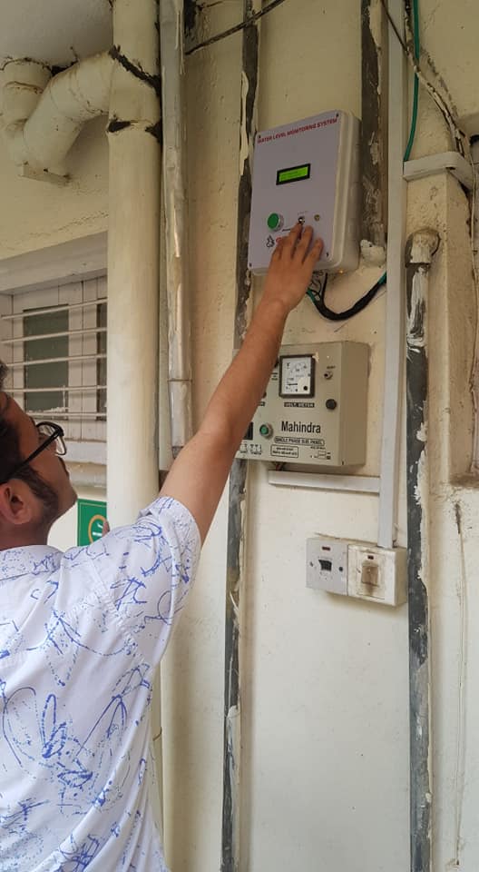
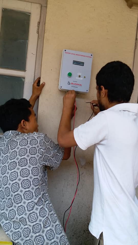
Field job was another daunting task but more fun. We installed the product in several places; Tamakoshi Hydropower Head Office, hotels, residential homes, Himal Refrigeration Offices and more.
The technical struggle was always beautiful. But working as a fresher to get your products sold was challenging. Convincing the donor was not easy. Manufacturing in bulk was not good idea, we could not guarantee they would be sold, high risk! We could not afford our own drilling machine, we tried to get one on our own but did not work out. The relays were not easily available that made our manufacturing very volatile. A fresher startup was fun and the learning curve was massive but there were hurdles. That's life. So we say it was sweet.
More technical tuning can be done to the entire board, networking among boards is our next technical struggle. We might deploy a microprocessor possibly Raspberry Pi. Hey, Pis are powerful. Maybe our project gets more power and we build more.